Foreword
Oil painting protection is an important part of the protection of cultural heritage across the world. Oil painting usually consists of a canvas fixed to a wooden or metal frame, oil paints and a layer of clear protective varnish. The varnish plays an important role in protecting the oil painting. Small cracks inevitably appear in the varnish over time due to the impact of temperature, humidity, and transportation, among other conditions. Once the expansion and deterioration of cracks in the varnish speed up, the aging of the whole oil painting accelerates accordingly. Therefore, research on cracks in oil paintings has always been one of the most-talked-about topics in oil painting protection.
Studies show that under certain lighting conditions or in laser cleaning antique oil paintings, small damage may be caused to the surface of oil painting, or the expansion of existing cracks may accelerate. Therefore, Shanghai University, the Palace Museum, the Institute of Electronic Structure and Laser of the Foundation for Research and Technology-Hellas (IESL-FORTH) of Greece, as well as other organizations, collaboratively leveraging the analysis techniques and scientific research collaboration platform of the Joint Laboratory, adopted digital holography for the experimental research on the growth of cracks in materials by focusing on the Dammer varnish that serves as the protection layer of oil paintings. The stimulation of crack growth is powered by laser irradiation, so as to simulate the growth of leaf-tip-shaped cracks in varnish under laser irradiation.

Figure 1. Distribution of common small cracks in oil paintings
Basic principles of digital holography
Digital holography (DH) is an interferometric imaging technique that uses digital image acquisition devices to directly record the diffraction light field of the measured object and performs numerical reconstruction of the diffraction light field through digital processing technology, obtaining relevant parameters of the measured object. The diffraction light field contains the intensity and phase information of the measured object, making the availability of three-dimensional information a unique advantage of digital holography. In addition, digital holography is featured by being microscopic and non-destructive with real-time imaging.
Design of an experimental system and sample making
The integrated optical path system of laser irradiation and digital hologram recording is shown in Figure 2. SC-Pro multi-spectral pulsed laser is used as the system’s light source, with the output wavelength ranging from 430 nm to 2,400 nm and a full-band operating power of 8W. The image acquisition device is a CCD (DHC-MER-500-7UM) camera, with the size of a single pixel being 2.2μm×2.2μm and the number of pixels in a pixel array being 1,544 (H) × 1,944 (V). In the system, the reflector M1 can be translated along the direction perpendicular to the optical axis: When the reflector M1 moves to the position of the solid line, the optical path LASER-M1-M4-L3 irradiates the sample, while the focal length of the convex lens L3 is 150mm, enabling concentrated irradiation from the light source. The Mach-Zehnder off-axis holographic interference optical path is formed when the reflector M1 moves to the position of the dotted line. After the laser beam is expanded and collimated by the spatial filter SF, it is divided into two beams by the prism BS1. One beam is irradiated through the reflector M2 to form the object beam of sample cracks, and the other beam passes through the reflector M3 to serve as the reference beam. The object beam and reference beam are expanded and amplified after passing through the convex lenses L1 and L2 respectively and merged through the prism BS2 and interfere on the CCD surface to form a hologram.
In the system, “p” is the focal length of the convex lenses L1 and L2, which is 120mm, while “q” is the distance from the rear focal plane of the convex lenses L1 and L2 to the photosensitive surface of the CCD. According to the principle of lens imaging, the L1-enabled magnification of the sample is q/p, and the beam expansion magnification enabled by the convex lenses L1 and L2 is 1.976. In other words, the measured object will be magnified by 1.976 times in the hologram recording process.
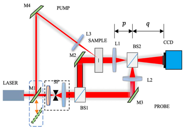
Figure 2. Schematic diagram of laser irradiation & digital holographic interferometric light path system (LASER-M4-L3 is the irradiation light path)
The experiment consists of two steps. Step 1: Use different wave bands, such as near-ultraviolet, visible light and near-infrared bands, to irradiate the cracked sample with laser for the photosensitivity analysis experiment of the material; Step 2: conduct a crack growth analysis experiment by irradiating the cracked sample with laser in a sensitive band range based on the results of Step 1. The sample preparation method in the two steps of the experiment is the same, and the photo of the sample is shown in Figure 3. Samples in Figure 3(a) and (b) are cracked samples with Dammar varnish which were used in the above experiment respectively. Meanwhile, for better comparative analysis, a crack-free sample coated with Dammar varnish as shown in Figure 2(c) was made as well for the crack growth analysis experiment. In the experiment, the recorded wavelength of the hologram was 633nm, and the frequency of irradiation laser was 5Mhz. The irradiation each time lasted 5 minutes.
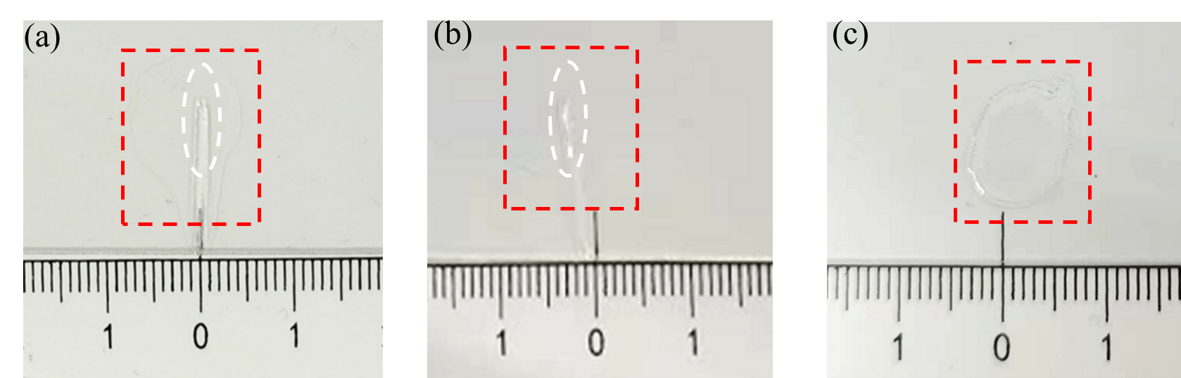
Figure 3. Samples for the experiment: (a) Cracked sample 1; (b) Cracked sample 2, (c) Crack-free sample
Experimental analysis of crack growth under laser irradiation
In the first step of the experiment, the irradiation bands used were near-infrared laser, visible light laser, and near-ultraviolet laser. To ensure enough irradiation power in place, two wavelengths were selected for each band to form a mixed light source. The process of the experiment was as follows: For the cracked sample shown in Figure 3(a), the hologram in its original state was firstly recorded. Then a mixed light source with wavelengths of 740 nm and 750 nm were used to irradiate the sample, and a hologram was recorded. Then the sample continued to be irradiated by a mixed light source with wavelengths of 430 nm and 440 nm and a hologram was recorded as well. Finally, the sample was irradiated by a mixed light source with wavelengths of 500 nm and 510 nm, and a hologram was recorded accordingly. The above-mentioned holograms were numerically reconstructed to obtain wrapped phases of the cracks in each state as shown in Figure 4(a)-(d) in sequence. By observing the phases in red dotted line boxes in these figures, we found that the phase changes of the top positions of cracks were most obvious after the irradiation by the mixed light source with wavelengths of 740 nm and 750 nm. Therefore, compared with lasers in visible light band and near ultraviolet band, the laser in near infrared band has a greater impact on the crack growth.
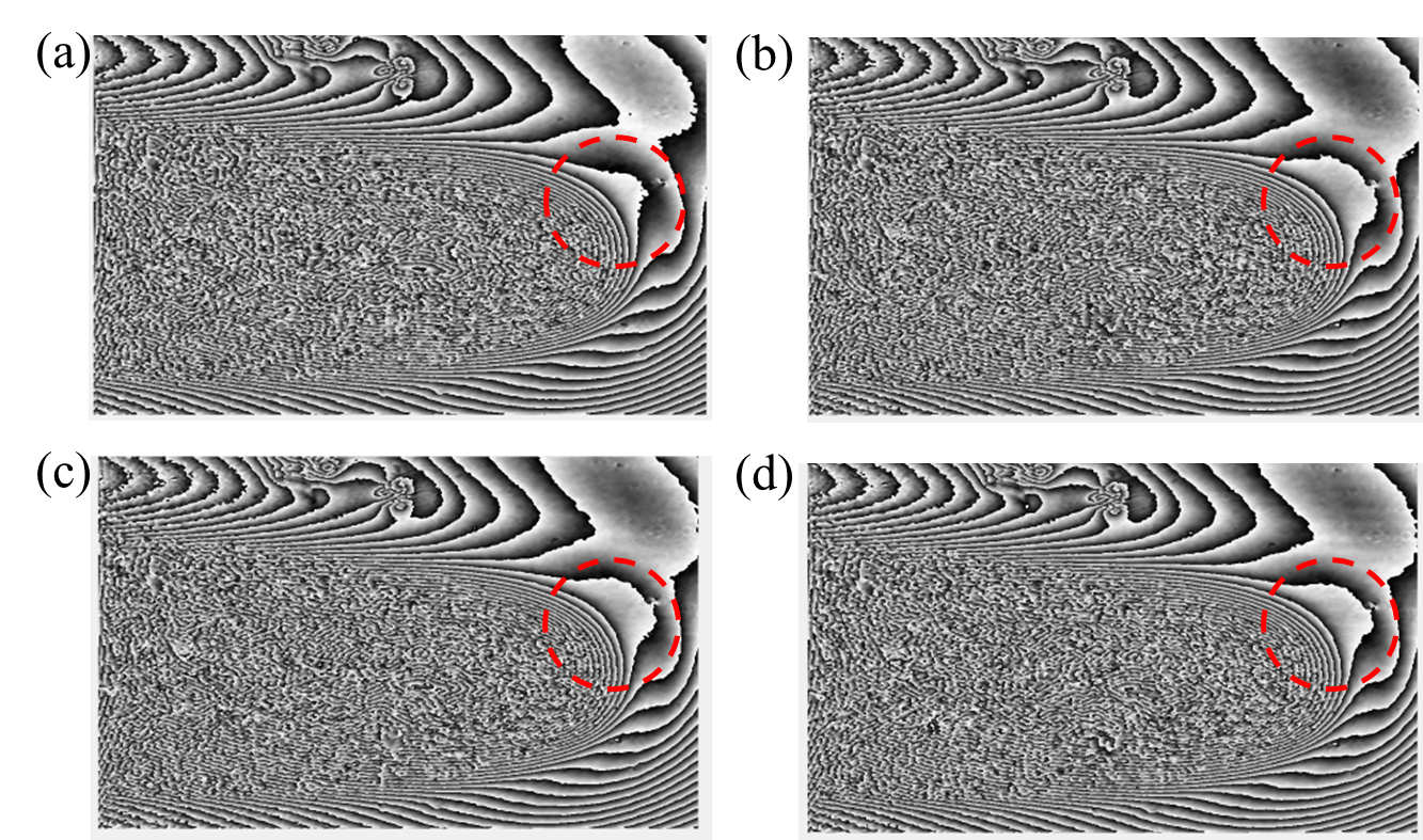
Figure 4. Reconstructed phases in holograms of the crack growth under the irradiation of light sources in different wavelength bands: (a) initial state; (b) 740 nm + 750 nm laser irradiation; (c) 430 nm + 440 nm laser irradiation; (d) 500 nm + 510 nm laser irradiation.
In the second step of the experiment, four mixed light sources in the near-infrared band with wavelengths of 740nm + 750 nm, 840nm + 850 nm, 940nm + 950 nm and 1,040nm + 1,050 nm were used to irradiate the cracked samples shown in Figure 2(b) with laser. The irradiation each time lasted 5 minutes, and the above process of hologram recording, and numerical reconstruction was repeated every time. The phase changes of crack growth after irradiation with light sources with different wavelengths were shown in Figure 5(a)-(d) in turn. To visualize the crack growth after irradiation, the No. 457, No. 1625, and No. 2525 pixels on the X-axis coordinates were selected, and then the intercepts along the Y-axis were extracted respectively. The intercepts at the same pixel position were reflected in the same picture as shown in Figure 6(a), Figure 6(c) and Figure 6(e), through which we could see that those cracks grew to varying degrees after the laser irradiation. The experiment process for the sample without cracks as shown in Figure 2(c) was repeated, and the experimental results were shown in Figure 6(b), Figure 6(d) and Figure 6(f). The result has shown that a crack-free sample will not be destroyed under the same laser irradiation for cracked samples.
Based on the pixel sizes and the system’s calibrated magnification, quantitative calculations were performed to quantify the crack growth for each group in Figure 6(a), Figure 6(c) and Figure 6(e). See results in Table 1. From the calculation data in Table 1, we can see that when the head of the leaf-tip-shaped crack was irradiated, the growth distance of the middle and tail parts of the cavity in the tested material also changed with the wavelength. It is fair to conclude that the crack’s head part is more sensitive to the change of the irradiation wavelength than the middle and the tail parts; when irradiated by lasers in the same band, the growth distance of the middle and tail parts of the crack is greater than that of the crack’s head, but the growth direction of the crack’s head is clearer.
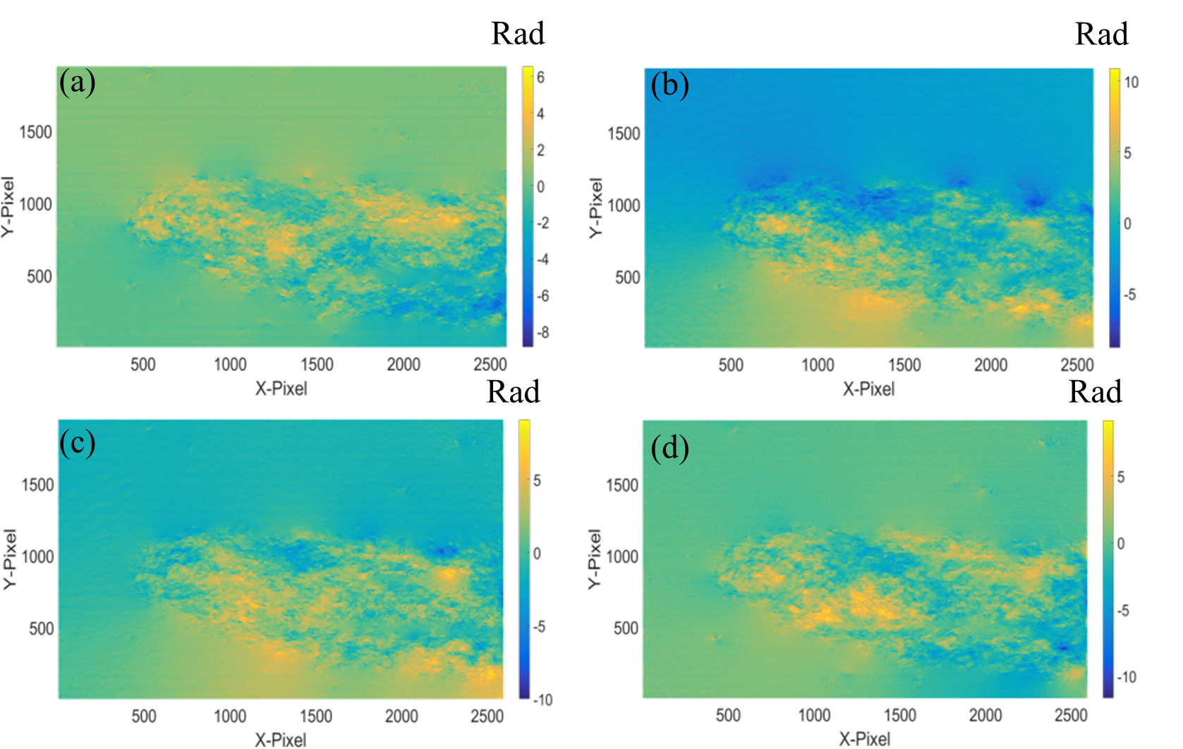
Figure 5. Phase changes of crack growth under irradiation of light sources in the near-infrared band: (a) After irradiation at 740 nm + 750 nm; (b) after irradiation at 840 nm + 850 nm; (c) after irradiation at 940 nm + 950 nm; (d) after irradiation at 1,040 nm + 1,050 nm.
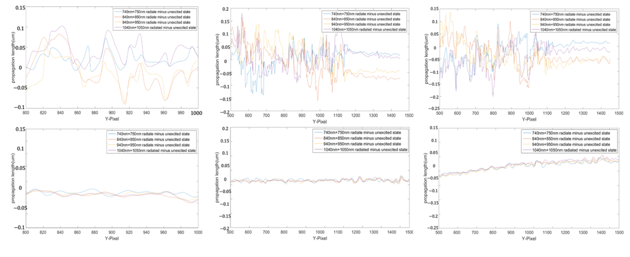
Figure 6. Sectional diagrams of phase changes of crack growth at different positions under irradiation of light sources in the near-infrared band (upper: samples with cracks; lower: crack-free samples):
(a)-(b) X = 457;(c)-(d) X = 1625;(e)-(f) X = 2525
Table 1. Crack extension distance of experimental groups and control groups under irradiation with different wavelengths (unit: µm)

Summary
Through an experimental study on laser irradiation of Dammar varnish cracks based on digital holography, we have found that if tiny cracks exist in the protective coating of oil paintings, crack growth is likely to occur at the tip of the crack under infrared radiation, leading to further deterioration of the coating which in turn causes more damage to the oil painting. Therefore, to better protect the oil painting, infrared light should be avoided as much as possible in the environment where oil paintings are preserved. When cleaning antique or fragile oil paintings with lasers, it is critical to use infrared lasers with caution to avoid irreversible damage to artworks. The digital holography system mentioned in this study is small in size, easy to integrate and carry, making it suitable to be applied to the on-site protection of cultural relics and research in the future. In addition, this study has proved that digital holography has unique advantages in the detection of defects of cultural relics. In the future, we will try to use digital holography for the research on tiny defects on non-transparent objects.
This research has recently been published online in Applied Sciences, a SCI journal from MDPI.
Link to the published research:
https://www.mdpi.com/2076-3417/12/15/7799


website: www.dpm.org.cn